When designing a system, do you ever feel lost about how to express the relationships between elements? It can feel especially difficult in the early stages of design when the relationships are not yet clear. I, too, had no idea where to start at first. However, by understanding just a few key relationships in SysML, you can represent even complex systems in a much more organized way. Today, I'll clearly and easily explain the most fundamental yet important concepts: Dependencies, Allocate, and Comment! 😊
1. Dependencies: The Loose but Flexible Link 🔗
A dependency is one of the most commonly used relationship types in SysML or UML modeling. As the name suggests, it's used when one element (the client) cannot function properly without the capabilities of another element (the supplier). It's incredibly useful in the early stages of design when the details of the relationship are still unclear.
While it has the advantage of flexibility, it's a semantically weak link, so it's often replaced by more specific relationships as the design becomes more concrete. However, its flexibility allows you to quickly structure initial ideas.
- Client and Supplier: It signifies that the client element depends on the supplier element, meaning if the supplier changes, the client may also be affected.
- Modeling Flexibility: Used when the details of a relationship are undecided, making design changes easier.
- Traceability and Impact Analysis: It's used to establish traceability between two elements and to automatically analyze the impact of design changes.
📝 EA Example: Representing Dependencies in a BDD
In a BDD (Block Definition Diagram), a dependency is shown with a dashed line and an open arrowhead pointing from the client to the supplier. For example, let's assume we need to control an SMPS via serial communication, but haven't decided which communication protocol to use, as shown in the diagram below. In this case, we can model that the SMPS block has a dependency on the 'MCU Serial Communication Interface' block.
By doing this, when the communication method is finalized later, you can easily find this dependency and change it to a more specific relationship, right?
2. Allocate: The Bridge Connecting Function and Structure 🌉
The allocation relationship is a crucial modeling technique that connects a system's behavior (Activity) to the structure (Block) that performs it. In simple terms, it clearly defines 'which block performs which function.' This relationship allows for an integrated understanding of the system by linking functional requirements with physical components.
Using allocation relationships, systems engineers can perform tasks like functional decomposition, responsibility assignment, and design verification much more efficiently. By breaking down the functionality of a complex system into manageable parts and defining how each part is allocated to a specific block, you can reduce design flaws and verify that requirements are accurately met.
📝 EA Example: Allocating a System Hard Reset Behavior
For instance, imagine a behavior (Activity) where the system performs a hard reset when a Watch-Dog timer expires due to a system malfunction. This 'System Hard Reset' activity can be allocated to the respective structures (Blocks) like MCU, SMPS, and Watch Dog. By using the allocation relationship this way, you can clearly express which specific structural elements implement an abstract behavior.
Tip! Using the 'Traceability' window in Enterprise Architect (Start → All Windows → Design → Trace) is super convenient for seeing at a glance which elements a specific block is related to!
3. Comment: Breathing Life into Your Model with Notes ✍️
When modeling, there are often times when you need to convey additional information or design intent that can't be expressed by the diagram alone. This is where Comments come in. You can think of it as being just like adding comments to your code. Using comments effectively can enhance the comprehensibility of your diagrams and facilitate smooth communication with others.
📝 EA Example: Creating Smart Comments with Hyperlinks
In EA, you can make your comments even more powerful. For example, by dragging and dropping a specific diagram into the BDD window and selecting 'Hyperlink', you can create a link that navigates directly to that diagram.
- From Toolbox → Common Elements, add a Note and enter a description (e.g., "Go to Battery Input BDD").
- Use a Note Link to connect it to the relevant element.
- Place the pre-made Hyperlink on top of the Note. (If it's hidden, right-click → Z-Order to adjust its position).
- Select both the Note and the Hyperlink, then right-click → Group Elements to group them.
Now, just by clicking the comment, you can navigate directly to the related diagram, which dramatically improves the readability and navigation efficiency of your diagrams!
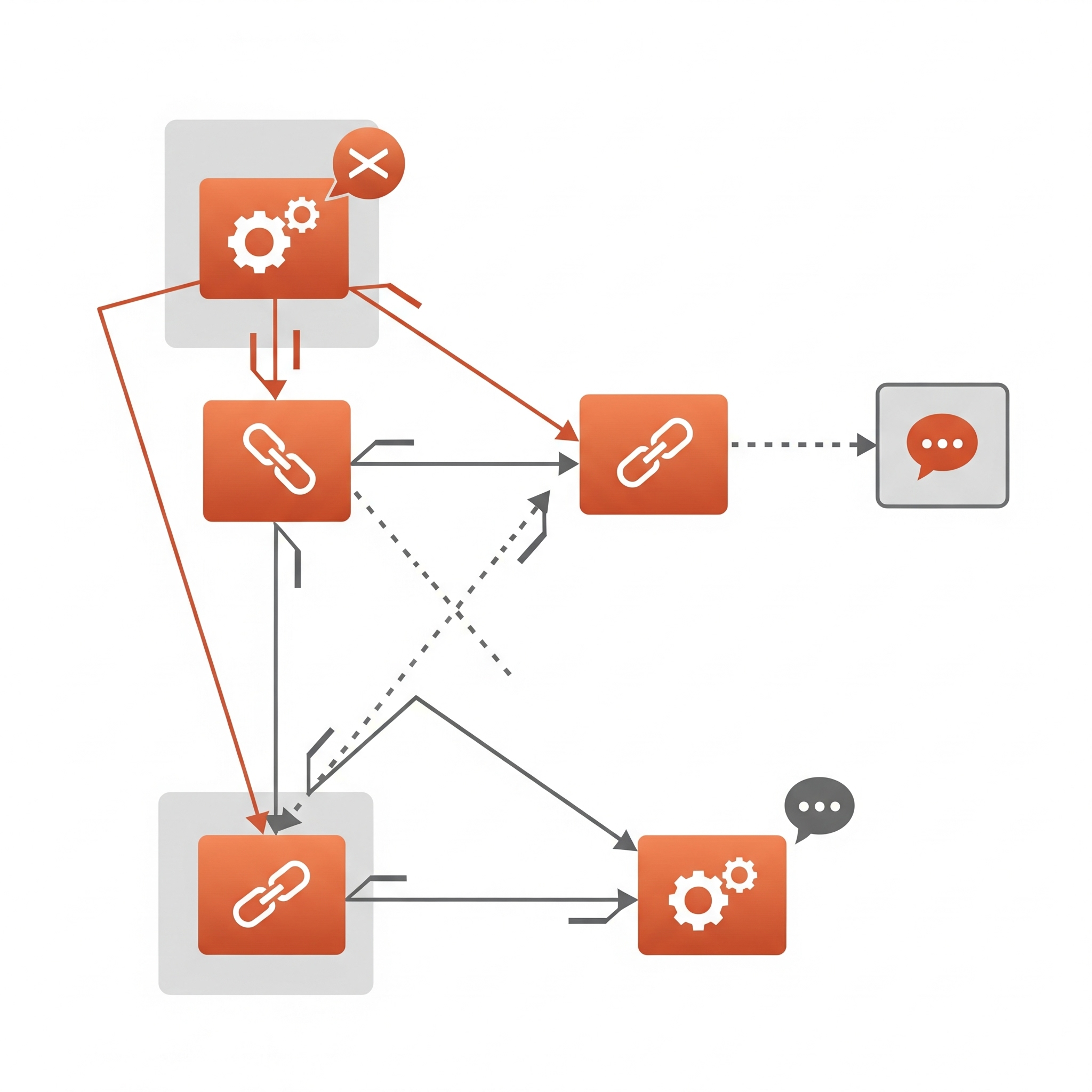
SysML Core Relationships at a Glance
Frequently Asked Questions ❓
SysML modeling might seem a bit complex at first, but by mastering the three concepts we learned today—dependency, allocation, and comment—you'll be able to create much clearer and richer diagrams. Give your system designs a boost! If you have any more questions, feel free to leave a comment below~ 😊